
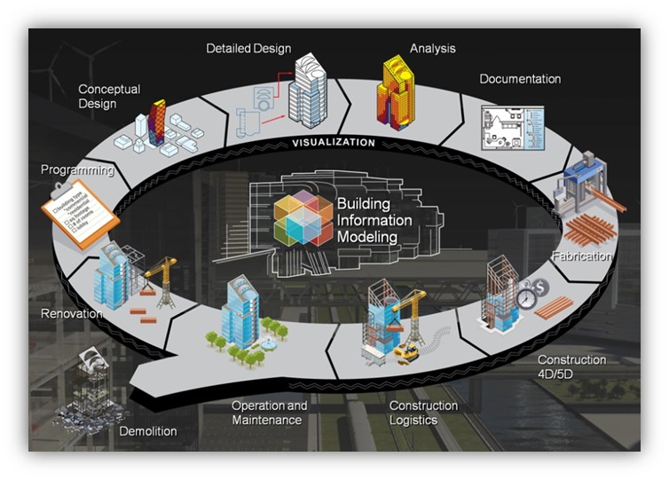
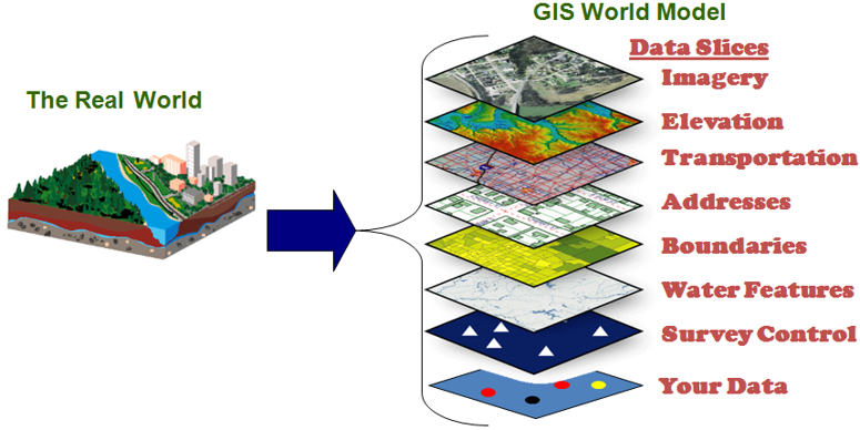
 BIM provides a solution for the interoperability in the AEC industry by providing an information backbone throughout the building lifecycle. Using BIM, different parties involved in the building process can work on a common platform, where the cost of information sharing is much less. While BIM aims to solve the problem of interoperability between stakeholders within the AEC industry, the integration of BIM with other systems, such as GIS, is becoming increasingly important. In the AEC industry, it has been reported that more than 80% of information could be referenced to the geographical information (Kim et al. 2012).
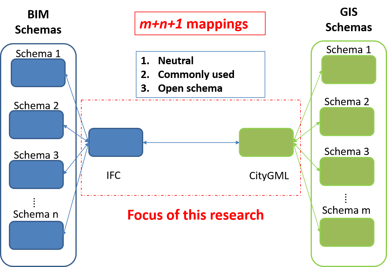
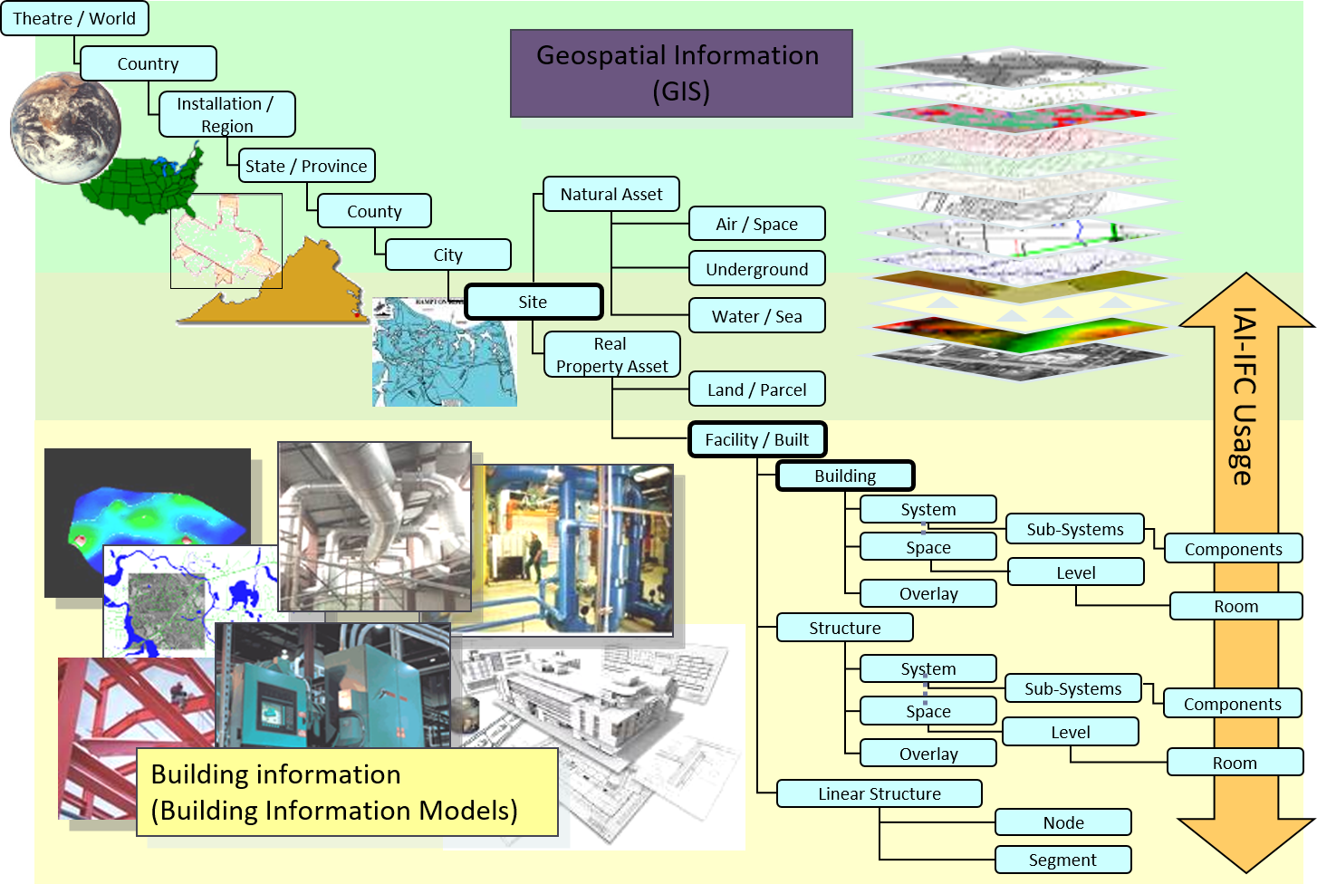
 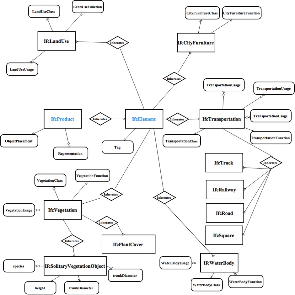 As shown in the figure, we developed a new ontology. Since a domain terminology list was generated for the GIS domain, it is possible to identify not only what are contained in IFC 4, but also the missing items to represent the domain concepts in the schema. With reference to the domain terminology list, we identified a number of concepts that were not hit by any entity definitions in IFC 4 for the GIS domains. For example, for all the 128 domain terms in GIS, there are 69 terms that were not hit by any definitions of IFC classes. It shows that the newer version of IFC cannot fulfill the data modeling requirement for GIS as compared to the domain schemas. Analyzing these zero-hit terms could provide a clue for further development of IFC towards complete modeling of the GIS domain. The results of the zero-hits mainly refer to road, railway and tunnels for the GIS domain. Based on the zero-hit domain terminologies and the schema of CityGML, we proposed an extension to the IFC 4 schema. The extension to the IFC schema for GIS is added mainly in the domain layer and the interoperability layer.
 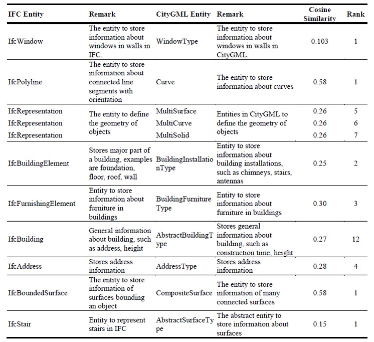 As shown in the figure, the linguistic-based method can generate reliable mapping candidates. The linguistic-based method compares the definitions and names of entities to generate mapping candidates, and entities referring to the similar content will have similar descriptions. The recall at the ranking threshold can reach 0.375, which means that by inspecting the first 100 candidates from the result, we could find 37.5% of the true matches. Considering the large number of entities in IFC (1008) and CityGML (607), the results from the linguistic-based method narrow the search space and reduce the human effort for mapping discovery. The linguistic-based method does not require the domain knowledge. As the methodology suggests, the linguistic-based method is performed on the basis of syntax comparison, in which people need not to know all the terminology from both domains. This feature of linguistic-based method indicates that it could be further applied to other schema mapping problems. Moreover, the Term Frequency and Inverse Document Frequency are also applied in the process, which generate a dictionary of words used in one domain and there frequency. This terminology pool could be further analyzed and used for other schema mapping problems. The linguistic-based method could also suggest candidates for 1-to-M mapping. The traditional mapping methods on the entity level only considers the entity names and may not be able to find mapping between one entity and many entities. For instance, the entity “AbstractOpening” in CityGML could be mapped to “IfcWiindow” or “IfcDoor”, but the mapping could not be discovered by name to name comparison. The linguistic-based mapping, which utilizes the definitions of entities, could broaden the scope of comparison and generate more 1-to-M mapping results. Another example from the linguistic-based mapping is the mapping between “AbstractBoundarySurfaceType” entity in CityGML with IFC BRep entities such as “IfcBoundedSurface”, “IfcFaceOuterBound”, “IfcFaceBound”, “IfcBoundingBox”, and “IfcClosedShell”. The 1-to-M mapping could be discovered in a threshold of 25.
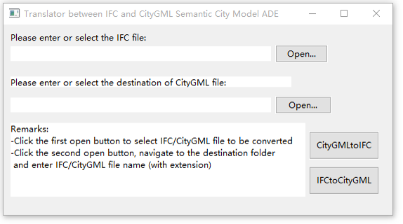
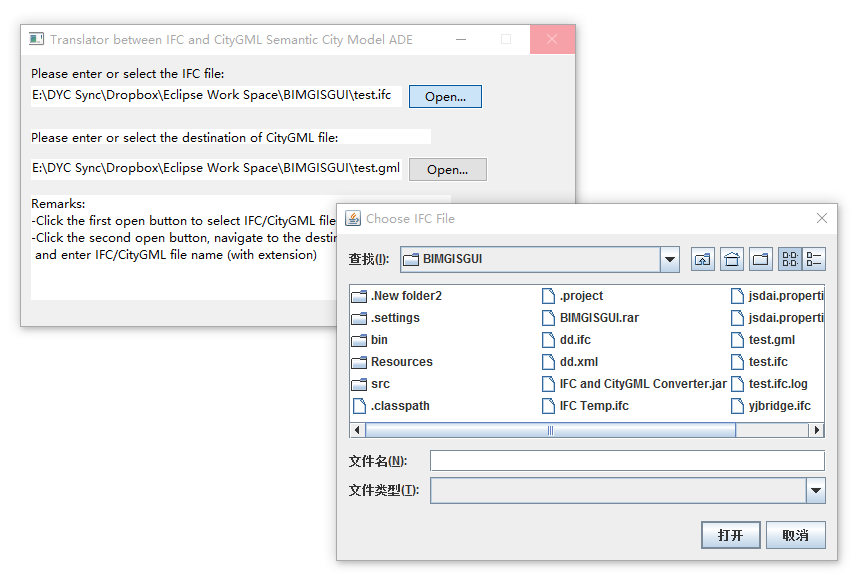
 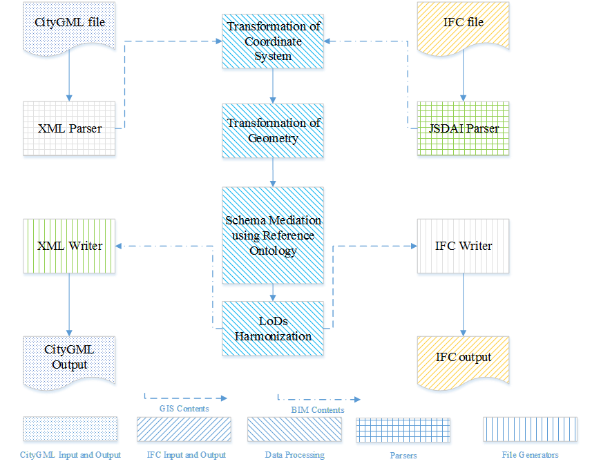 We proposed a methodology for mapping between IFC and CityGML considering transformation of both geometric and semantic information, as shown in the figure on the left. The proposed methodology will achieve the goal of bi-directional mapping between IFC and CityGML. A reference ontology called Semantic City Model which carries and transforms the information from the two data standards was developed as the core mapping module. With the reference ontology and the instance-based mapping rule generation, the bi-directional mapping between IFC and CityGML could be achieved. The parsers for both CityGML file and IFC file were built based on the JAVA platform. The parser for CityGML was CityGML4j developed by Nagel (Gröger et al. 2012). CityGML4j can parse CityGML files and generate an object-tree in the JAVA platform. Data inside the CityGML files can thus be accessed. The parser for IFC was the JSDAI, which is an Application Programming Interface (API) for reading, writing and runtime manipulation of object oriented data defined by an EXPRESS based data model (Döllner and Buchholz 2005). By building IFC entity libraries using JSDAI, JAVA can also parse the IFC files into an object-tree structure. The CityGML4j and JSDAI were also used as the writer for CityGML and IFC files, respectively.
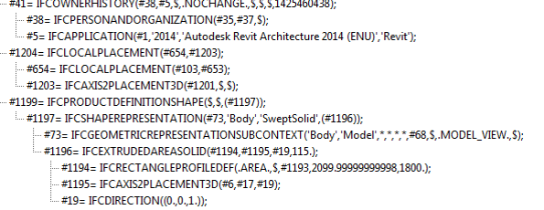
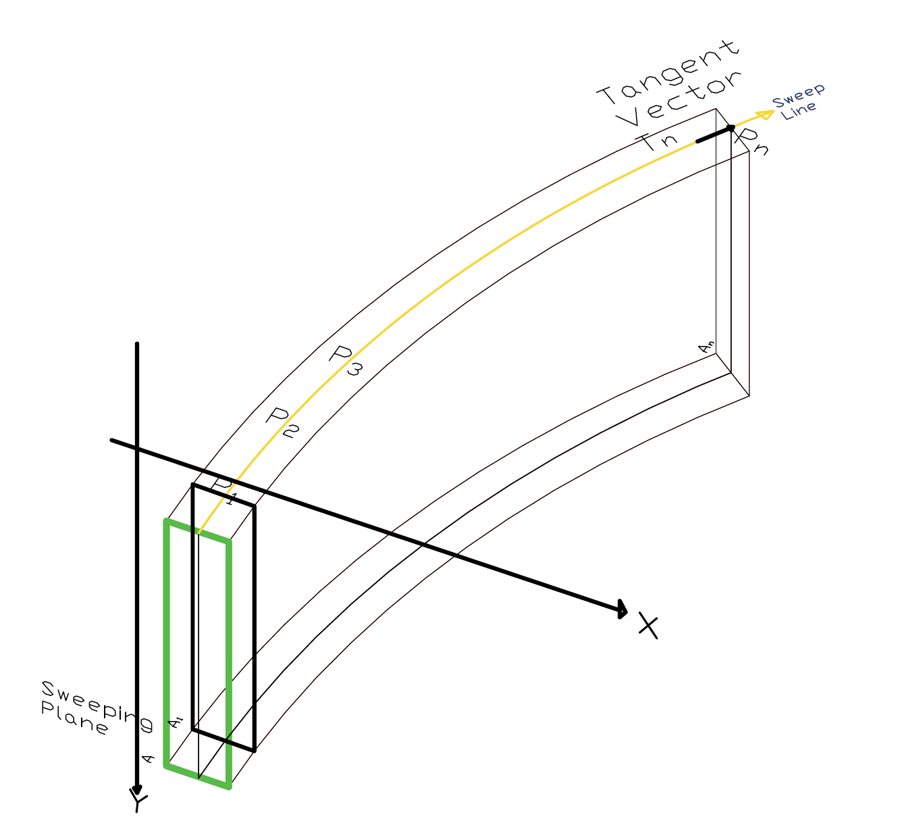 IFC employs a local placement system in which objects are defined in local coordinate systems. The local placement system is further referenced to other local placement systems. For example, the local placement system of a wall may refer to the local placement system of the building, while the building may refer to the world coordinate system. The local placement system ensures that each building component is uniquely defined and is easy for copying of information. For scenarios such as multiple similar walls in the same building storey, one might just have to change their local placement system and retain the other information. However, CityGML uses a world coordinate system in which all the coordinate values of objects are absolute and do not refer to other objects. The transformation from a local placement system to a world coordinate system may be achieved by a method proposed by (Wu and Hsieh 2007). Another critical problem for the geometry transformation is the transformation between BRep and CSG/Swept Solid. IFC utilizes different methods to represent solids, such as storing their boundary surfaces (BRep), storing the cross-section of solids and the swept direction, or using combination of solids (CSG). CityGML uses only the BRep, in which all the objects are represented by surfaces. In this study, the IFC BRep to CityGML BRep and IFC Swept Solid to CityGML BRep were developed for data mapping. The IFC BRep to CityGML BRep function extracts the coordinates of the IFC BRep from the parser and translates the coordinates to world coordinate system in CityGML using the coordinate system transformation function. The IFC Swept Solid to CityGML BRep transformation is the most commonly seen geometric transformation. A function is developed to use the coordinates from the sweeping planning and the sweeping line to generate new BRep surfaces, as illustrated in the figure above.
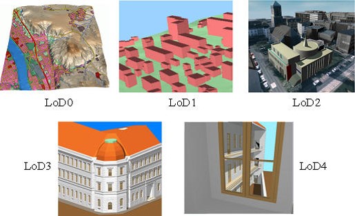
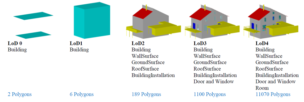 Among all the common 3D GIS standards available nowadays, the City Geography Markup Language (CityGML) has the most sophisticated definition about LoDs. CityGML is a common modeling language for 3D city objects launched by the Open Geospatial Consortium (OGC) in 2008. CityGML defines city objects such as buildings and infrastructure in terms of topographic object information, semantic information and appearance properties (Gröger and Plümer 2012). CityGML also supports five distinct LoDs for buildings in city models ranging from 2.5 dimensional regional models (LoD0) to detailed building models with interior information (LoD4). The LoDs in CityGML contain many features such as building interiors and furniture that LoDs defined in other GIS schemas do not. CityGML defines five distinct LoDs for efficient visualization and data analysis (Gröger et al. 2012). Different LoDs can be stored for the same object simultaneously, which provides different resolution for viewing and analysis. Although the official CityGML Encoding Standard gives descriptions about each LoD, no clear definitions were offered, so users often create models in different LoDs according to their own understanding. In addition, the CityGML Encoding Standard did not provide methods to transform between LoDs.
 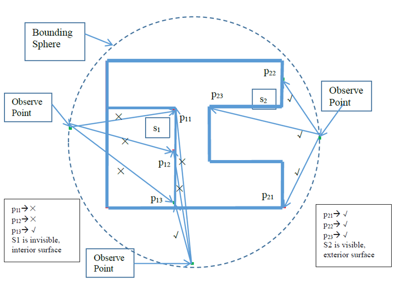 Extraction of the exterior shell of a building is a common step when trying to simplify digital building models. Although the exterior features and interior features should be clearly defined in CityGML, some of the input models may not necessarily distinguish the features as interior or exterior. Models transformed from other data formats such as IFC or KML may not contain information of whether the surface is interior or exterior. There is a need for finding the exterior shell for some of the input models. It is also an essential step in LoD4 to LoD3 transformation. As discussed in Section 5.2, the common way of extracting the building envelope is to track the footprint. However, this footprint tracking method is not applicable to buildings with roof overhanging parts as the roof overlays the projection of walls. In Fan et al. (2009), the authors tried to solve this problem by calculating the centroid of building and comparing the distances of each surface to it. However, this proposed method is not applicable for buildings with a non-convex shape as the centroid does not necessarily reflect the “center” of the building. The new exterior shell extraction algorithm uses the same idea as Ray Tracing algorithm, yet to determine the exterior surfaces out of a detailed input model, the view points to shoot the rays will be changed according to model input. After data processing, the CityGML models are broken into many planar surfaces with corresponding semantic information. Our goal is to find the exterior shell of these surfaces by checking their visibility from the exterior. Our algorithm works as follows: first, find the exterior, which in our case is a bounding sphere of the building. This is calculated in O(1) time for each building. Next, the visibility of each surface against points on the bounding sphere is checked. The visibility of the surfaces is determined using the Ray Tracing algorithm, assuming that the observing rays shoot from points on the sphere. If three randomly generated points from the surface are all visible from the bounding sphere, the surfaces are considered visible and thus on the exterior shell of the building. To avoid fault judgments where some of the exterior surfaces are not visible form the bounding sphere, the program would also check the contiguity of the generated exterior shell. If holes exists in the surfaces, the program will double check the surfaces inside the holes to see if they are exterior. The process is illustrated in the figure above.
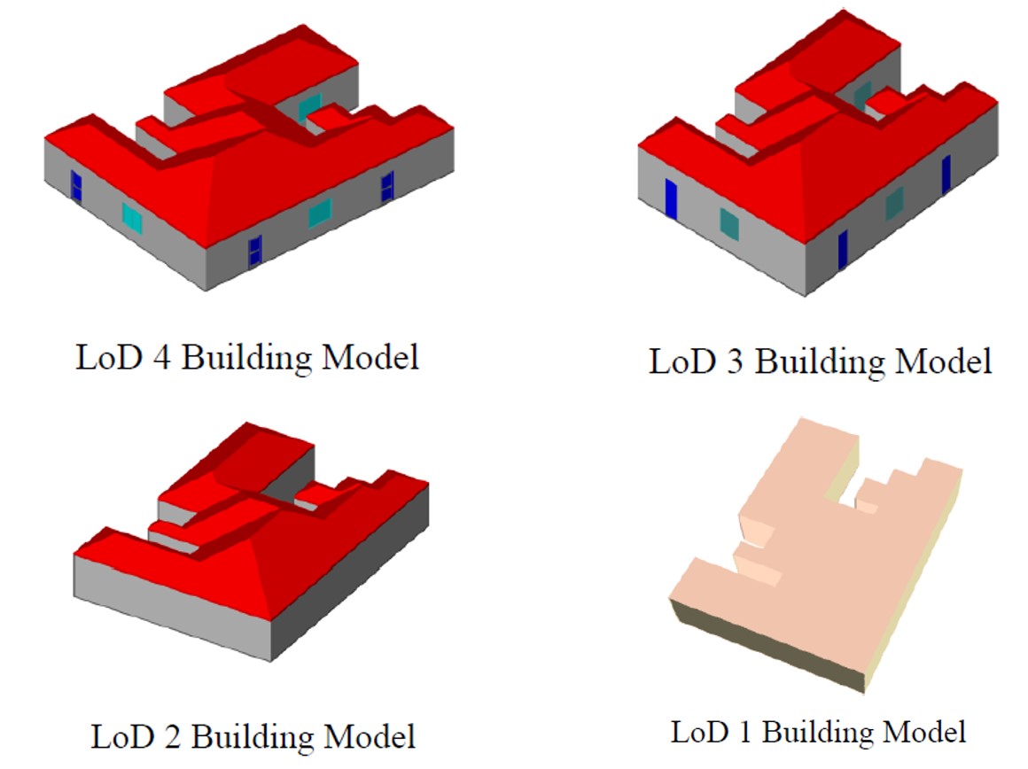 The proposed LoD transformation framework was implemented in a Java application and tested using a computer with a dual-core Intel i5-2400 CPU (3.1 GHz) and 4GB RAM. The test data sets came from the CityGML models generated from BIM models. All the input data sets were LoD4 models. The LoD transformation was performed in a down-grading fashion in which higher LoDs were converted into lower LoDs. The developed LoD transformation framework could successfully transform LoD4 models to different LoDs without information loss, even for buildings with complex geometry. The transformation among LoD4, LoD3, LoD2 and LoD1 involved few geometric transformations. Therefore, the running time of the LoD transformation shows a linear relationship with the model size. The transformation between LoD4 and LoD3 involved the exterior shell extraction, with the quadratic running time and memory consumption to the model size. Nonetheless, the running time for most ordinary dwelling 3D CityGML models was less than two seconds on our platform. For a two-story house model, the maximum running time was only about 4 seconds. The proposed exterior shell extraction algorithm is a critical step in the LoD4 to LoD3 transformation. The traditional footprint correction method or the method finding the building centroid is not applicable for complex 3D building models. Buildings with non-convex building envelope cannot be handled by such algorithms. The exterior shell extraction algorithm in our framework, on the other hand, uses all the surfaces of the models as input and tries to find surfaces that are visible from the outside of building. These surfaces are the exterior surfaces of the buildings and should be kept in LoD3 models. The exterior shell extraction algorithm considers all the possible cases of visibility of surfaces against the bounding sphere, so it is applicable for even non-convex shapes. The complex non-convex models indicate the effectiveness of the algorithm. The surfaces inside the corner of buildings can be discovered and kept in the generated LoD3 models.
 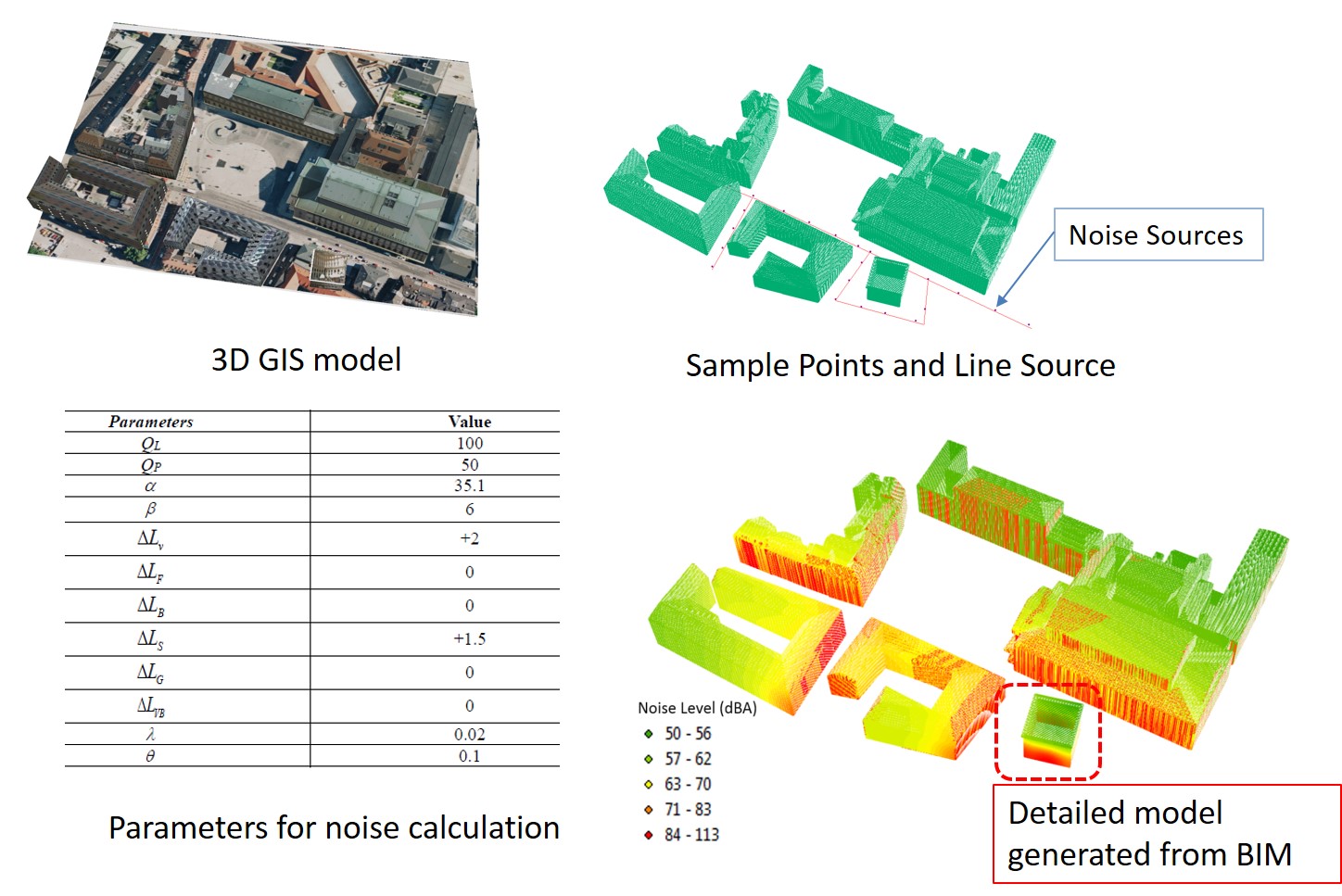 The noise levels for all the sample points could be calculated and stored in a file-based database. ArcGIS could show 3D noise maps with different colors representing different noise levels. 3D noise maps show the noise distribution in the 3D environment with respect to the noise sources. In a macro scale, urban planners could use this 3D noise map to see the influence of noise on an existing infrastructure or planned infrastructure. If some areas with exceeding noise levels were observed by 3D noise mapping, several countermeasures could be planned and executed, such as placing noise barriers or controlling the traffic flow for certain roads. In a micro scale, in a virtual design process for single buildings near traffic sources, designers could see whether the noise level indoors meets the design requirements. For example, as recommended by the World Health Organization (WHO), the noise level of a small room should not exceed 35 dBA to ensure speech intelligibility (World Health Organization 1999). In our platform, a GUI (Graphical User Interface) is also provided to allow users to judge whether the indoor noise level is acceptable or not and to provide updating suggestion. The updating suggestion is based on the calculation process for maximum noise level in indoor environments. The GUI could suggest modifications in boundary surface materials or traffic control options. Designers could then update the model using BIM software by our developed updating system in the BIM-GIS integration engine.
 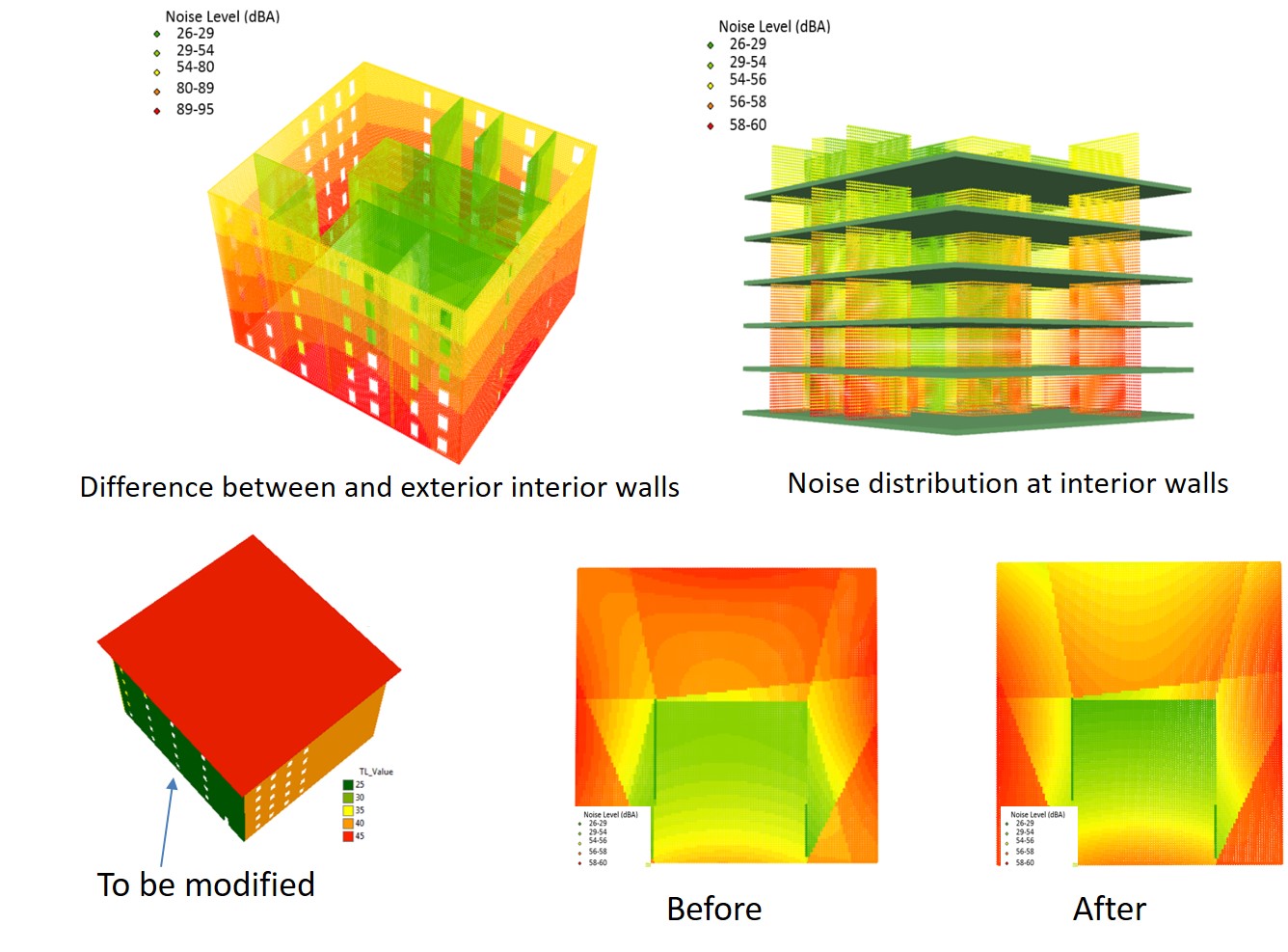 The 3D noise mapping tools are based on the Italian C.N.R. model and were implemented on ArcGIS and Autodesk Revit for demonstration purpose. An integration engine for BIM and GIS was developed in order to extract data from BIM for noise simulation and import them to the 3D GIS environment. The proposed framework contains four module that are able to generate sample points from input 3D GIS model, calculate outdoor noise considering first order reflections, and calculate indoor noise levels considering transmission loss, and report simulation results. A model updating function was also developed with the BIM-GIS integration engine, which allows updating of GIS models using BIM software. Two use case scenarios were presented to demonstrate the proposed framework could benefit both urban planning and decision making in VDC process for single buildings. The issues of LoD in simulation and accuracy of results were also discussed. In the future, we aim to improve the accuracy of the 3D noise mapping framework by investigating a methodology for selecting region specific parameters in the Italian C.N.R. model. For example, in Hong Kong, the Environmental Protection Department (EPD) provides traffic noise map for major roads (Wing et al. 2006). The data from EPD can be used to calibrate the parameter in C.N.R. model in order to make the framework applicable in Hong Kong. The results can be further improved by considering more times of reflection using parallel computing and more powerful computing infrastructure.
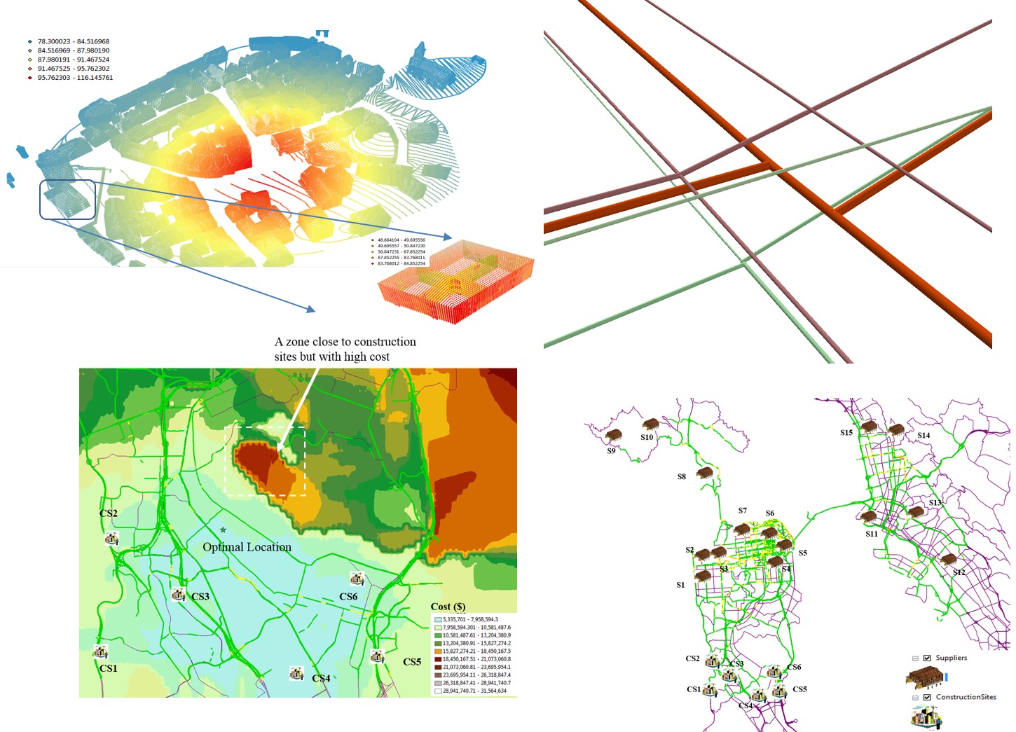
 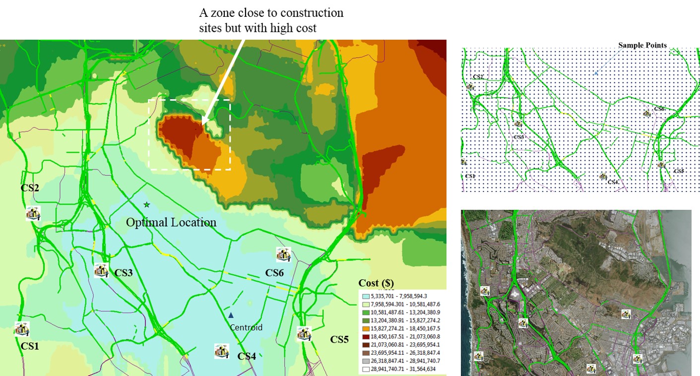 As shown in the figure on the left, we can find consolidartion centers with low cost. By using data from BIM and GIS, we formulate the three problems in mathematical form and provide solutions to these problems. Specifically, we make the following contributions to these three problems: firstly, we prove that selection of suppliers should not only consider factors such as delivery distance or unit price solely. Secondly, we should understand that the number of material deliveries has impacts on the total invoice cost of the supply chain, and we provide a Monte-Carlo Simulation solution to this problem. Thirdly, we prove the necessity of setting up of consolidation centers given the congested sites and long delivery distances using mathematical modelling. And finally, we provide a solution to the location-allocation problem of the setting up of consolidation centers. It is noticeable that all the contributions could not be made without the data inputs and analysis functions in BIM and GIS.
 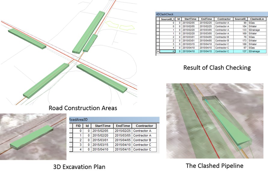 An integrated BIM-GIS framework for improving the information management and analyses of underground utilities by government authorities has been proposed and implemented. The framework is in 3D and therefore provides more capabilities than the current 2D-based utility management systems. A data schema was proposed for underground utility information management. Different functions such as model regeneration, design checking and construability analysis have been developed. Model updating using the developed BIM-GIS integration engine is also supported. The proposed framework was successfully implemented and tested using ArcGIS and Revit BIM software in the preliminary study. This framework is still under development and does not support the modeling of utility connections and rectangular pipelines. In the next phase of this research, the authors aim to seek cooperation with local utility management authorities to implement and verify the framework. The computer-generated model regeneration models and clash analysis reports will be compared to manual records and onsite measurements. The UUI data schema will be tested to see its coverage and effectiveness in communicating utility information.
 Publications from this project:
1. Cheng, J. C.; Lu, Q.; Deng, Y., Analytical review and evaluation of civil information modeling. Automation in Construction 2016, 67, 31-47.
2. Deng, Y.; Cheng, J. C.; Anumba, C., A framework for 3D traffic noise mapping using data from BIM and GIS integration. Structure and Infrastructure Engineering 2016, 1-14.
3. Deng, Y.; Cheng, J. C.; Anumba, C., Mapping between BIM and 3D GIS in different levels of detail using schema mediation and instance comparison. Automation in Construction 2016, 67, 1-21.
4. Deng, Y.; Cheng, J. C. P., Construction supply chain coordination leveraging 4D BIM and GIS integration. Proceedings of the CIB World Building Congress 2016, Tampere, Finland 2016.
5. Cheng, J.; Deng, Y.; Anumba, C., Mapping BIM schema and 3D GIS schema semi-automatically utilizing linguistic and text mining techniques. Journal of Information Technology in Construction (ITcon) 2015, 20, 193-212.
6. Cheng, J. C.; Deng, Y., An Integrated BIM-GIS Framework for Utility Information Management and Analyses. Congress on Computing in Civil Engineering, Proceedings, 2015 ASCE International Workshop on Computing in Civil Engineering, IWCCE 2015; University of Texas at AustinAustin; United States 2015, 2015 (January), 667.
7. Cheng, J. C.; Deng, Y., Modeling and management of utility information using a 3D BIM-GIS integration framework. The Second International Conference on Sustainable Urbanization (ICSU 2015) 2015.
8. Cheng, J. C.; Deng, Y.; Anumba, C., Mapping BIM schema and 3D GIS schema semi-automatically utilizing linguistic and text mining techniques. Journal of Information Technology in Construction 2015, 20, 193-212.
9. Cheng, J. C. P.; Deng, Y., Automatic transformation of different levels of detail in 3D GIS city models. International Journal of 3-D Information Modeling 2015, 4 (3), 1.
10. Deng, Y. Mapping of BIM and GIS for Interoperable Geospatial Data Management and Analysis for the Built Environment. Hong Kong University of Science and Technology, 2015.
11. Deng, Y.; Das, M.; Cheng, J. C. P., A framework for integrating energy simulation data in building information modeling. Proceedings of the 3rd International Conference on Civil Engineering, Architecture and Sustainable Infrastructure (ICCEASI 2015), Hong Kong, China 2015.
12. Cheng, J. C.; Deng, Y.; Das, M.; Anumba, C., Evaluation of IFC4 for the GIS and Green Building Domains. Computing in Civil and Building Engineering (2014) 2014, 2216-2223.
13. Deng, Y.; Cheng, J., Integrating BIM and GIS for Urban Planning Purposes Considering Acoustics. In The Twenty-seventh KKHTCNN Symposium on Civil Engineering, Shanghai, China, 2014.
14. Cheng, J. C. P.; Deng, Y.; Du, Q., Mapping Between BIM Models and 3D GIS City Models of Different Levels of Detail In 13th International Conference on Construction Applications of Virtual Reality, London, United Kingdom, 2013.
15. Cheng, J. C. P.; Deng, Y., Mapping BIM models and 3D GIS models using schema matching and linguistic methods. The 12th International Conference on Construction Applications of Virtual Reality (CONVR 2012), Taipei, Taiwan 2012.


 Jack C.P. CHENG (鄭展鵬) PhD , Stanford University
 .jpg) Chimay J. Anumba, FREng., Ph.D., D.Sc., Dr.h.c., P.E.
Chimay J. Anumba, FREng., Ph.D., D.Sc., Dr.h.c., P.E. Yichuan Deng, PhD